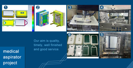
Plastic Intake Manifold Mold
1、Product mix:
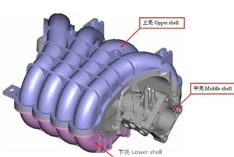
(1)Upper shell
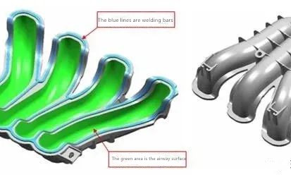
Welding reinforcement: the welding reinforcement shall be smooth, so the welding surface shall be made into an integral electrode as far as possible to prevent problems during EDM processing.
Airway surface: the airway surface is required to be smooth, so whether EDM processing or CNC processing, it must be ensured that there is no knife snapping or overcutting.
The other side of the upper shell is generally the visible side of the intake manifold. Generally, customers will require surface pitting. These surfaces are usually the rear surface of the mold, so there will inevitably be thimbles, so it is required that the thimbles should be smooth and anti rotation must be done.
(2)Middle shell
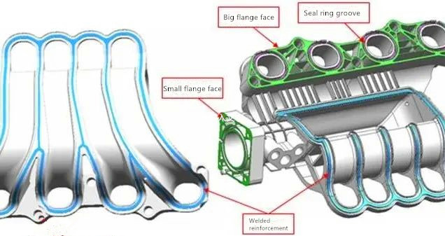
Nozzle: the nozzle is used to connect the hose. Generally, the nozzle will have an inverted buckle to fasten the hose to prevent it from falling off. Therefore, it is required that the parting line of the nozzle should not be too obvious and there must be no sharp edges, otherwise it is easy to cut and damage the hose. It is best to consider that there is no parting line at the assembly part in the design.
Seal ring groove: This is used to assemble the seal ring after welding. Considering that the transportation after assembly prevents the seal ring from vibrating and falling, the inner wall around the seal ring groove cannot have too much slope. At the same time, the depth of the seal ring groove directly affects the sealing effect, so the depth of the seal ring groove is also very important.
Large and small flange faces: the flatness requirements are high. If the deformation of these two faces is too large, the sealing effect will also be affected.
Airway hole: the same requirements as the airway hole of the upper shell.
(3)Lower shell
The lower shell, like the upper shell, has the same function of welding ribs and airway holes, so the requirements are exactly the same as the upper shell.
2. Intake manifold mold design and manufacturing standards:
(1) Plastic materials:
The material of the intake manifold is usually pa6+30%gf, which has good fluidity, so it is easy to have bad problems such as trapped gas and sharp edges, so the exhaust should be sufficient in the mold design. The parting surface needs to be provided with exhaust slots every 30 mm. For the closed deep bone, it must be provided with inserts for exhaust. The general size of the exhaust slot is 6 mm wide and 0.02 mm deep.
(2)Key knowledge of mold:
Gate
The intake manifold product is complex and the material of the product is easy to produce large deformation, so the design of the glue inlet point is the focus of the whole set of mold design. The design of glue inlet points has the following principles:
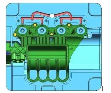
1) The glue feeding point must ensure that the glue feeding of each airway is uniform. Usually, there is one glue feeding point for each airway, as shown in the following figure:
2) Go from the part with more glue to the part with less glue
3) From the part with thick glue position to the part with thin glue position
4) There should be no weld marks or trapped gas in the parts related to the airway, otherwise the bursting pressure of the product will be affected
5) According to mold flow analysis, select the glue feeding method that has the least influence on product deformation
6) All the glue inlet points must be made into an insert structure to facilitate the subsequent adjustment of the position or size of the glue port
7) The flat side gate or needle valve gate is used to directly inject glue into the product, which is conducive to injection molding and filling. Generally, the intake manifold mold does not use the way of dispensing port or submerged port. See Figure 6 above.
8) The gate must be easy to break, and the fracture section must be flat. Size reference: 1.5~2.0 mm deep and 4~8 mm wide. The specific size depends on the size of the product.
Cooling
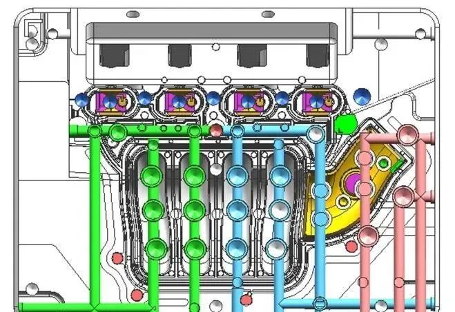
The melting temperature of pa6-gf30 is about 260, and the temperature of the forming mold is about 80 ℃. At the same time, the glue thickness of the product is thick (2.5~3 mm) and very uneven. The thickest glue thickness can reach about 8~10 mm, so cooling is also very important for the inlet manifold mold. Water transportation design also has the following principles:
- The distance between the water transportation of the front and rear mold cores and the glue position is about 20 mm, and it is as uniform as possible. Water wells can be used to cool the protruding parts. The distance of each water transportation should not be too long, and the number of water wells in each group should not exceed 4. The diameter of water channel shall not be less than 12 mm, and the diameter of water well shall not be less than 20 mm, which shall be as large as possible.
- For parts with thick glue position or concentrated heat, the cooling must be sufficient. Beryllium copper inserts with excellent heat dissipation effect can be considered to transport water to take away the accumulated heat.
- Because the heating temperature of the hot runner system is too high, there must be a separate group of water to cool the hot runner system. However, it should be noted that in order to prevent the heat loss of the hot runner system, all the mold surfaces matched with the hot runner system should be as few as possible, especially the hot nozzle sleeve sealing rubber surface, which is generally about 5 mm. If it is too many, it is easy to have problems such as hot nozzle plugging or nozzle sticking.
- Because the mold temperature is high, the a/b plate and hot runner plate usually need to be cooled by water to prevent the guide post or other precision parts from being damaged due to high temperature or inconsistent temperature difference in the production process.
- As far as possible, each row position and inclined top should be cooled by water, and the diameter of the water channel should not be less than 8 mm.
Ejection
Because the hardness of pa6-gf30 material is high, the intake manifold mold generally will not have the phenomenon of top white and top high. It should be noted that the ejection should be balanced.